Here is another helpful little MATLAB script written by Prof. Kabal where I made a small modification. The script is basically a wrapper around MATLAB's waitbar function, displaying a typical progress bar such as pretty much every program in the existence of GUIs has ever had.
Using a single function, you set it up first with
ProgressBar(Frac, Delta, Title)
where Delta or Title are optional: default values are 0.01 and an empty title. Frac is the starting fraction of completion; typically this will be 0.
You update the value with
ProgressBar(Frac)
which will only update the window if the display will change by more than Delta: So, if Delta is 0.05, the display will only be redrawn if it changes the display by more than 5%.
Finally, call the function without arguments to close the pop-out window.
I made a simple modification to check if we really have a screen to display to: if not, the update operation displays a simple percentage on stdout (also controlled by Delta). I made this modification since I tend to run tasks remotely using ssh and screen. I found the code to check for a display here.
Get the script here: ProgressBar.m
Sporadic outbursts of things that have to do with research, electronics or coding that may or may not be DSP related.
ASCIIMath creating images
Saturday, September 24, 2011
Sunday, September 11, 2011
Real-time control of MATLAB using a MIDI controller
UPDATE 28/11/2014: this post is obsolete, I have created a better method and described it here.
Sometimes it's nice to set variables in MATLAB in real-time, using an actual physical knob. Like you can find on a MIDI controller.
MATLAB generally is not geared for real-time data input, and to the best of my knowledge, there is no MIDI library for input. So, I hacked up a shockingly simple way of getting controller status data into MATLAB: a small helper program passing data through the filesystem.
The helper program does very little: listen to the MIDI bus, if a controller message is seen, write it to a file in the /tmp directory. In particular, I name the files /tmp/cc/<number>, where <number> is the controller number. Since controllers can only take values 0–127, the files are one byte long.
The MATLAB side is equally simple. If you want to read controller value x, open /tmp/cc/x and read the first byte. Should the read fail, return-1, : let the calling program figure out what to do in that case (eg. read again or use the old value). The code is simply:
The race condition (MATLAB reading the file while it's being written) also returns-1, given the single-byte length of the file that is sufficient. Again, the calling program should handle it somehow.
The helper program
The actual reading of MIDI messages is messy, platform-dependent code that I'd rather not be writing myself. So instead I use the rtmidi package, developed just on the other side of the McGill campus; it works on Mac, Linux, and Windows. The helper program is a simple modification of the program qmidiin.cpp from the tests directory in the rtmidi distribution.
The code can be compiled the same way the other program in the tests directory are compiled, on my Mac it was g++ -O3 -Wall -I.. -D__MACOSX_CORE__ -o midicctmp midicctmp.cpp Release/RtMidi.o -framework CoreMIDI -framework CoreFoundation -framework CoreAudio. Note that the program will fail if the directory /tmp/cc does not exists; just create it manually, or modify the above code to create it at startup.
I have not yet tested it on Linux, but I see no reason for it to not work. I have an idea for a slightly more fancy event-based method, but that's for another post.
Sometimes it's nice to set variables in MATLAB in real-time, using an actual physical knob. Like you can find on a MIDI controller.
![]() |
| MIDI controller hooked up to my Mac |
The helper program does very little: listen to the MIDI bus, if a controller message is seen, write it to a file in the /tmp directory. In particular, I name the files /tmp/cc/<number>, where <number> is the controller number. Since controllers can only take values 0–127, the files are one byte long.
The MATLAB side is equally simple. If you want to read controller value x, open /tmp/cc/x and read the first byte. Should the read fail, return
function r = getCCval( n )
fname = sprintf( '/tmp/cc/%d', n );
f = fopen( fname, 'r' );
if f<0
r = -1;
return
end
r = fread( f, 1, 'uint8' );
fclose(f);
if isempty(r)
r = -1;
end
end
The race condition (MATLAB reading the file while it's being written) also returns
The helper program
The actual reading of MIDI messages is messy, platform-dependent code that I'd rather not be writing myself. So instead I use the rtmidi package, developed just on the other side of the McGill campus; it works on Mac, Linux, and Windows. The helper program is a simple modification of the program qmidiin.cpp from the tests directory in the rtmidi distribution.
//*****************************************// // midicctmp.cpp by Joachim Thiemann 2011 // modified from // qmidiin.cpp by Gary Scavone, 2003-2004. // // read MIDI queue and create files in // /tmp/cc with controller state // //*****************************************// #include#include #include #include "RtMidi.h" #include #define SLEEP( milliseconds ) usleep( (unsigned long) (milliseconds * 1000.0) ) #include bool done; static void finish( int ignore ){ done = true; } void usage( void ) { // Error function in case of incorrect command-line // argument specifications. std::cout << "\nusage: midicctmp \n"; std::cout << " where port = the device to use (default = 0).\n\n"; exit( 0 ); } int main( int argc, char *argv[] ) { RtMidiIn *midiin = 0; std::vector message; int nBytes; double stamp; FILE *f; // Minimal command-line check. if ( argc > 2 ) usage(); // RtMidiIn constructor try { midiin = new RtMidiIn(); } catch ( RtError &error ) { error.printMessage(); exit( EXIT_FAILURE ); } // Check available ports vs. specified. unsigned int port = 0; unsigned int nPorts = midiin->getPortCount(); if ( argc == 2 ) port = (unsigned int) atoi( argv[1] ); if ( port >= nPorts ) { delete midiin; std::cout << "Invalid port specifier!\n"; usage(); } try { midiin->openPort( port ); } catch ( RtError &error ) { error.printMessage(); goto cleanup; } // Ignore sysex, timing, or active sensing messages. midiin->ignoreTypes( true, true, true ); // Install an interrupt handler function. done = false; (void) signal(SIGINT, finish); // Periodically check input queue. std::cout << "Reading MIDI from port ... quit with Ctrl-C.\n"; while ( !done ) { stamp = midiin->getMessage( &message ); nBytes = message.size(); if (nBytes==3) { char fn[20]; if ((message[0]>>4)==11) { sprintf(fn,"/tmp/cc/%d",(int)message[1]); f = fopen(fn,"w"); fwrite(&message[2],1,1,f); fclose(f); } } // If queue empty, sleep for 10 milliseconds. if (nBytes==0) SLEEP( 10 ); } // Clean up cleanup: delete midiin; return 0; }
The code can be compiled the same way the other program in the tests directory are compiled, on my Mac it was g++ -O3 -Wall -I.. -D__MACOSX_CORE__ -o midicctmp midicctmp.cpp Release/RtMidi.o -framework CoreMIDI -framework CoreFoundation -framework CoreAudio. Note that the program will fail if the directory /tmp/cc does not exists; just create it manually, or modify the above code to create it at startup.
I have not yet tested it on Linux, but I see no reason for it to not work. I have an idea for a slightly more fancy event-based method, but that's for another post.
Tuesday, August 9, 2011
Conference Posters using LaTeX
A few students in the TSP lab have papers to present in poster sessions at INTERSPEECH 2011. Congratulations! In the past, the TSP Lab students used to use PowerPoint to create the posters - a bit of a kludge, and if the submitted paper was written using LaTeX, it might mean having to re-enter the equations (in addition to all the other annoyances of PowerPoint).
This pain can be avoided by doing the poster in LaTeX as well, as I did for my INTERSPEECH paper (see "Reconstructing Audio Signals from Modified Non-Coherent Hilbert Envelopes" on my research page). I used the a0poster package, and while it can be a bit daunting at first, with a good template it's quite easy to use. I've modified my own poster to be a small guide, with explanations: see inside the TSP Lab Template Package. It contains the a0poster class (probably an older version), and the McGill logo.
Friday, July 22, 2011
SIDshield prototype: test results
For those interested in this project (both of you!) :-) I finished the testing of the SIDshield prototype. Summary: It works! (Yay!) but with caveats and a few fixes are needed (booo!)
After cleaning, visual inspection and continuity check (see yesterday's post) I found I forgot 3 wires - one to connect the grounds together, and 2 for getting the 12V to the SID chip. Thus fixed, I populated the board with all chips except for the SID and applied power. Seeing no magic blue smoke escape, I measured the 12V supply, which looked very good (without load of course) giving me ~12.4V. All other signals on the SID socket looked good so I put it in, applied power again and verified the voltages again. Same as without load.
![]() |
| Arduino (under Protoshield) with SIDshield prototype fully populated |
Power Considerations
The SID needs up to 100mA on the 12V line (according to the datasheet), so about 1.2W of power. The TPS6734 has to produce that power from 5V, and thus needs to draw more than twice the current off that supply. Clearly, this is too much for a USB port, thus the Arduino must be connected to a power supply. Also take note that the barrel connector is going through a regulator with associated voltage drop (at least on my Arduino Diecimila) so your supply needs to give more than 5V.
A further complication is that the TPS6734 regulates really well for a range of input voltages; this means it has an effective negative resistance: if the input voltage drops (say, to 4V) it will draw more current; this could lower the voltage even further. We have a positive feedback loop, ending when the supply voltage drops below what the boost converter can use and we loose the 12V. Milliseconds later, the converter starts up again (since it did not draw any current and the supply recovered) and the process begins anew. Needless to say, this does not sound good on the output. So, give the poor SID a good supply!
One could argue of course that the better solution is to provide a good stable 12V supply and drop in a good old 7805 to supply the Arduino - this is why we build prototypes, right?
BTW, with all this power being sucked up, the SID gets pretty warm, I tell you...
Corrections and Changes to the Schematic
The circuit even when supplied with good power on the Arduino external power barrel connector gives a bit of noise when playing large amplitude sounds. This probably needs some resizing of capacitors when compared to the circuit given in the TPS6734 datasheet.
I also moved the reset line of the SID to a programmable (Digital Out) pin, and toggle that line in the SID library constructor.
The biggest error in the schematic posted in a previous post is that the capacitors on the input and output lines are far too small. 22pF? I have no idea how that got in there - they need to be about .1uF! I need to fix that on the board.
The hardware is thus effectively finished, needing just a few corrections. I will update the schematic eventually, including the boost converter. The main to-do is now some more code, especially to get steady timing, which is vital for good sounding vibrato, tremolo, and arpeggio effects - not to mention basic song timing.
However, there are a pile of other projects I've been itching to do...
The SID needs up to 100mA on the 12V line (according to the datasheet), so about 1.2W of power. The TPS6734 has to produce that power from 5V, and thus needs to draw more than twice the current off that supply. Clearly, this is too much for a USB port, thus the Arduino must be connected to a power supply. Also take note that the barrel connector is going through a regulator with associated voltage drop (at least on my Arduino Diecimila) so your supply needs to give more than 5V.
A further complication is that the TPS6734 regulates really well for a range of input voltages; this means it has an effective negative resistance: if the input voltage drops (say, to 4V) it will draw more current; this could lower the voltage even further. We have a positive feedback loop, ending when the supply voltage drops below what the boost converter can use and we loose the 12V. Milliseconds later, the converter starts up again (since it did not draw any current and the supply recovered) and the process begins anew. Needless to say, this does not sound good on the output. So, give the poor SID a good supply!
| The multimeter shows the draw on the 5V line, including the Arduino. The scope shows the noise on the 12V line, which is 1Vp-p and about 100mV RMS. Noise control needs to be improved. |
BTW, with all this power being sucked up, the SID gets pretty warm, I tell you...
Corrections and Changes to the Schematic
The circuit even when supplied with good power on the Arduino external power barrel connector gives a bit of noise when playing large amplitude sounds. This probably needs some resizing of capacitors when compared to the circuit given in the TPS6734 datasheet.
I also moved the reset line of the SID to a programmable (Digital Out) pin, and toggle that line in the SID library constructor.
The biggest error in the schematic posted in a previous post is that the capacitors on the input and output lines are far too small. 22pF? I have no idea how that got in there - they need to be about .1uF! I need to fix that on the board.
The hardware is thus effectively finished, needing just a few corrections. I will update the schematic eventually, including the boost converter. The main to-do is now some more code, especially to get steady timing, which is vital for good sounding vibrato, tremolo, and arpeggio effects - not to mention basic song timing.
However, there are a pile of other projects I've been itching to do...
Wednesday, July 20, 2011
SIDshield prototype almost done
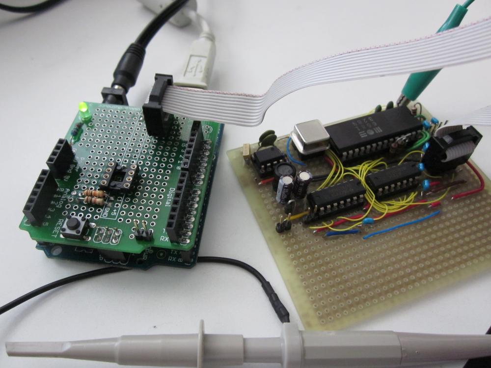
I've finally gotten around to doing some electronics again, and finished wiring up the full prototype of the SIDshield for Arduino. Soldering and wiring got done yesterday, later today I will go over the whole thing very carefully to check for shorts and broken connections/wires, make sure GND and power are everywhere they're supposed to be. Then, I will plug in everything except for the SID and apply power, to make sure the magic smoke stays in; only then will I plug in the SID since it's a not-easily-replaced chip.
It's not a "real" schield in this format, but I decided it was better to separate it from the Arduino using a ribbon cable. Still, the whole thing is in a 8cm x 5cm rectangle.
I'll post the results of checking and testing either tonight or tomorrow.
Update: results here.
| Component side |
It's not a "real" schield in this format, but I decided it was better to separate it from the Arduino using a ribbon cable. Still, the whole thing is in a 8cm x 5cm rectangle.
| Solder side |
Update: results here.
Wednesday, July 13, 2011
Geek happiness is... a box from the parts store
My day was made this morning when I received my order from Digi-Key. Yes, this contains the parts to finally build the real prototype of the SIDshield, including the 5V-to-12V boost converter, a 8-pin DIP chip TPS6734. And, of course, the needed inductor, diode, and caps. I also got the 1 MHz oscillator (ECS-2100), so the board can be completely self-standing.
What I forgot to order was the 14-pin and 8-pin sockets - but those I can get at the local store, I just have to find the time to bike there...
Wednesday, June 8, 2011
Ancient history: my first Amiga mod
Currently, I am in the process of cleaning up my collection of old computers. I came across one of the pieces I'm still quite attached to (since it was my main computer for a considerable while): my Amiga - one of those before they had model numbers (now called the Amiga 1000). One of the reasons it is special to me is because it was the first major surgery I performed on a computer, which furthermore _had_ to work since I didn't have any other computer at that time. The hack? Expand it to have 1 Megabyte of RAM.
The stock A1000 came with only 256k of RAM, and was quite famous at the time for being able to multitask in that limited environment. However, noone ever left it at that. Almost every A1000 has the added 256k expansion in the front slot, for a more usable 512k. From Commodore's perspective, that was as much as once could expand the A1000 without using the external side expansion slot.
However, if you had the guts to do it you could add another 512k inside the A1000 without a PCB. This involved piggybacking RAM chips on the existing onboard RAM, and hacking RAS, CAS, and address lines to select the chips appropriately. This is what I did - and I have no idea where the instructions came from. A quick search of Aminet and the Fish Disk index didn't find anything. The hack was done in about 1991, if I remember correctly.
How much I have learned since then... But the lesson I learned is not to be afraid of modding hardware!
The stock A1000 came with only 256k of RAM, and was quite famous at the time for being able to multitask in that limited environment. However, noone ever left it at that. Almost every A1000 has the added 256k expansion in the front slot, for a more usable 512k. From Commodore's perspective, that was as much as once could expand the A1000 without using the external side expansion slot.
However, if you had the guts to do it you could add another 512k inside the A1000 without a PCB. This involved piggybacking RAM chips on the existing onboard RAM, and hacking RAS, CAS, and address lines to select the chips appropriately. This is what I did - and I have no idea where the instructions came from. A quick search of Aminet and the Fish Disk index didn't find anything. The hack was done in about 1991, if I remember correctly.
| This is the inside of the A1000, with the RF shield removed. Nothing special to see except for one extra small green wire attached to the WOM (kickstart) daughterboard. |
| Underneath the daugtherboard, it's a bit more messy. Note that I did label all the wires, but instead of heat-shrink tubing I used bits of electrical tape for insulation. |
| This shows the detail of 2 RAM chips piggybacked onto the original RAM, with a socket. |
| Now this is truly ugly. Obviously, I had no idea about proper electronic construction back then. Yes, these are resistors directly soldered to IC pins. |
| But, 20 years later, it still works! The screen titlebar actually says "896456 free memory' |
| This is the only repair I have to do. The wire on the daughterboard is close to breaking off. |
Subscribe to:
Posts (Atom)