ASCIIMath creating images

Showing posts with label prototyping. Show all posts

Wednesday, November 1, 2017

Halloween Raspberry Pi project

Halloween is a great time to do projects if you have kids.  There is a lot of fun to be had building animated things for displays or costumes.  In our case, Madeline and I collaborated on a great costume for our son, who wanted to go as a Robot.  She found some shiny material and sewed it up, and I build an animated control panel.

The Rπ0 controls a IIC-connected OLED display (128x32) and 9 LEDs via the GPIOs. I could theoretically have used an Arduino - but the OLED display is 3.3V only, and I only have 5V Arduinos (I know I can just underclock them, but not during development).  Thickness was also a factor - the Rπ0 is VERY flat.

The panel is built mostly of Moosgummi (craft foam rubber), and I mounted my Raspberry Pi 0 into it.  The Rπ0 and all the other stuff is mounted in a sandwich of Moosgummi sheets with strips of Moosgummi around the edge.  Power and development (eg. changing the scrolling message or the blink pattern) is done trough a gap, through which a (short) USB cable is fed.  The LEDs are connected trough 150 Ohm resistors directly to the GPIOs.

The SD card has Raspbian Stretch Lite on it, to which I added the Adafruit SSD1306 Python library.  The Python script (placed in a Gist here) running the display and the LEDs sits in the (FAT-formatted) boot partition, and is called from rc.local.  Once that was all in place, I used the Read-Only Raspbian script to make the system read-only; this way I can just pull the power once the trick-or-treating is done.  The script on the boot partition can still be edited at will by remounting /boot read-write (or pulling the SD card and editing it on a different computer!)  The Rπ0 acts as a USB Ethernet gadget, and I can just ssh into it.

Life lesson learned: Mounting blinking LEDs on your kids makes them very easy to find at night! Note to self: next time, add lights to the back (of the kids) as well.

Wednesday, May 3, 2017

Resampling in Python: Electric Bugaloo

In a previous post, I looked at some sample rate conversion methods for Python, at least for audio data.  I did some more digging into it, and thanks to a note by Prof. Christian Muenker from the Munich University of Applied Sciences I was made aware of scipy.signal.resample_poly (new in scipy since 0.18.0).  This lead me down a bit of a rabbit-hole and I ended up with a Jupyter Notebook which I'm not going to copy-paste here since there is quite a bit of code and some LaTeX in there.  Here is the link to it instead.

For the impatient, here are the interesting bits:

def resample_poly_filter(up, down, beta=5.0, L=16001):
    
    # *** this block STOLEN FROM scipy.signal.resample_poly ***
    # Determine our up and down factors
    # Use a rational approximation to save computation time on really long
    # signals
    g_ = gcd(up, down)
    up //= g_
    down //= g_
    max_rate = max(up, down)

    sfact = np.sqrt(1+(beta/np.pi)**2)
            
    # generate first filter attempt: with 6dB attenuation at f_c.
    filt = firwin(L, 1/max_rate, window=('kaiser', beta))
    
    N_FFT = 2**19
    NBINS = N_FFT/2+1
    paddedfilt = np.zeros(N_FFT)
    paddedfilt[:L] = filt
    ffilt = np.fft.rfft(paddedfilt)
    
    # now find the minimum between f_c and f_c+sqrt(1+(beta/pi)^2)/L
    bot = int(np.floor(NBINS/max_rate))
    top = int(np.ceil(NBINS*(1/max_rate + 2*sfact/L)))
    firstnull = (np.argmin(np.abs(ffilt[bot:top])) + bot)/NBINS
    
    # generate the proper shifted filter
    filt2 = firwin(L, -firstnull+2/max_rate, window=('kaiser', beta))
    
    return filt2

plt.figure(figsize=(15,3))
wfilt = resample_poly_filter(P, Q, L=2**16+1)
plt.specgram(scipy_signal.resample_poly(sig, P, Q, window=wfilt)*30, scale='dB', Fs=P, NFFT=256)
plt.colorbar()
plt.axis((0,2,0,Q/2))

Recycling my test sweep from the previous post, I get:
Sweep resampled using my own filter
But really, please read the Notebook.  Comments are welcome!

Monday, June 6, 2016

FFT-based Overlap-Add FIR filtering in Python

Here is a small Python function I've written (github), that might be useful if you're doing signal processing in Python.  The function implements the classic FFT-based Overlap-Add filtering, potentially saving a heck of a lot of processing time (assuming your filter is of sufficiently high order: usually about 128 taps).

For a thorough explanation of the algorithm, see the Wikipedia article.

I wrote this code as part of a lager ongoing project (gammatone filtering) that I will release eventually.  What I still have to add to this code is the ability to set and save state information (it's simply the part of the response cut off at the end of the function) and the ability to filter complex signals with complex filters (replacing rfft with fft).  Changes made in the latest version.

Wednesday, May 18, 2016

A simple scikit-learn classifier based on Gaussian Mixture Models (GMM)

When I started switching to Python for my work on CASA, it wasn't entirely clear to me how to use the sklearn GMM (sklearn.mixture.GMM) for classification.  Turned out a bit easier than expected (yay for scikit-learn!), but for others, here is my implementation of a class that behaves like the other classifiers (eg. sklean.svm.SVC).  All you need to decide is how many Gaussians you want to model your data with, and off you go.

Link to Github repo. A Jupyter notebook shows a sample use.

Why isn't something like this in sklearn yet?  Well, turns out someone did propose it already (no surprise) in a much more general way: see this discussion on GitHub.  (I myself was pointed there when I asked about my own code)  My bit of code is far more primitive, but I hope easier to understand.

Monday, February 8, 2016

GMM based localizer on custom ASIC model

The model interface hardware with the FPGA in-circuit emulator.
Lukas Gerlach (L) and Christopher Seifert (R) demoing their ASIC model setup, running realtime on a FPGA.

It's always nice to see one's own research code running on real actual hardware with live data rather than just having a simulation in MATLAB.  My colleagues over at the Institut für Mikroelektronische Systeme (IMS) of the Leibnitz Universität in Hannover presented a demo of their hardware at the Hearing4All winter plenary held last week in Soltau.  The code running on the hardware visible is a GMM based localizer originally written by Tobias May, but since heavily modified by myself.  The next step is that we'll write up exactly what we did to make this all work and how well it does - so look out for an article on this in the near future! It's one of the advantages of being at an intengrated cluster; at Hearing4All, pretty much everything related to hearing loss is being investigated: from basic ear physiology, to audiology, models, algorithms, clinical procedures, implants, and new ground-breaking hardware.


Thursday, July 2, 2015

A bit of Python path hackery

Like many people, I have a directory in $HOME for useful python code I write. Similar to MATLAB's "Documents/MATLAB" directory, I want those files to be easily available if I'm hacking new stuff. The typical way of handling this is to do:

import sys
sys.path.append('/path/to/my/dir')
       
 
but that is a bit ugly, and has the problem that if I'm doing an IPython Notebook (as I often do), this append function gets reevaluated if I reexecute the cell in which I do all my imports (since as I'm edition the notebook and adding stuff, I would do a lot). Besides I now have sys in my namespace.

I could just dump it into ".local/lib/python3.4/site-packages" (too hidden, outside the tree that is synced between machines), or link "Documents/Python" to that path, but then I don't want to have pip install stuff there, and also, there might be times I don't want "Documents/Python" to be in the path.

So here's my solution.  I place a file in ".local/lib/python3.4/site-packages" and ".local/lib/python2.7/site-packages" with a name like "LocalPath.py", and this file contains

       
import sys

myPythonDir = '/home/jthiem/Documents/Python'
if myPythonDir not in sys.path:
    sys.path.append(myPythonDir);
    
 
I can now do
       
import LocalPath
 
and have instant no-fuss access to my homebrew packages.  Now isn't that nice.

Monday, June 30, 2014

Samsung ARM Chromebook XE303 with VGA adapter - power problems

I have a Samsung ARM Chromebook (the 303 series) which is pretty nice, and I really like it for its size, weight and complete lack of fan and hard drive noise.
Samsung XE303C12-H01DE Chromebook: with 3G modem and
a German keyboard which I'm still not used to.

However, I need to give presentations on occasions.  No problem, I just get one of these:
HDMI to VGA adapter from DX.com (SKU 156981)
For less than $10, that's hard to beat.  Unfortunately, I found it doesn't work as-is with the Samsung Chromebook.  Already thinking I need to either give up on the idea of using the Chromebook for presenting or getting a more expensive adapter, I decided to try and see why the bloody thing doesn't work. I verified it does work with my Raspberry Pi, so the problem must be with the Chromebook - perhaps a power problem?  According to Wikipedia, HDMI should have +5V on pin 18.  I opened up the adapter, which can be done with nothing more than one's fingernail, running it along the seam around the VGA socket, then confirmed the absence of 5V on the HDMI port.  Lukily, getting 5V is no problem if you have a USB port nearby and here is my solution to this particular annoyance:
HDMI to VGA adapter with power bypass fitted
I take no responibility for damage you might be inflicting to your Chromebook or any other device you might want to use this mod on. Try this at your own risk, there is a good chance of frying delicate electronics. 
How to solder the power onto the adapter: +5 on
pin 18, ground to wherever convenient.
Basically, take a USB plug and solder two wires to just the outside pins.  Drill a hole through the plastic and the rubber fitting of the HDMI to VGA adapter (slide the insides out first!)  Solder the 5V wire to the pin 18 endpoint of the cable and the ground to a ground point on the adapter PCB.  Done!  I put a knot into the cable for strain relief, to prevent the solder points being ripped off.

That's it! It works nicely, although I don't think the adapter queries the monitor for modes, a decent selection is given to the ChromeOS as soon as the adapter is plugged in.  I've only tried it with one projector so far, but there is no reason it should not work with just about any that accept VGA signals.

Hopefully this information is useful to other (ARM) Chromebook users, but note this is a no-name adapter - yours may look entirely different.  Just remember these adapters are active devices which need power (even if very little), and since the Chromebook isn't delivering it on its HDMI port, you need to get it there somehow.

Thursday, May 29, 2014

A Sudoku solver in Python

I'm not that great at Python yet.  But practice makes perfect, so just to see if I can do it, I wrote this Sudoku solver in Python (needs v3).  The algorithm is my own though I don't think it is very (or at all) novel, just actually looking for other solvers would spoil the fun!

The implementation is also probably overly byzantine, mostly due to the way the state is stored.  This is done as follows: at the bottom is a list of states for each symbol in a given cell, the states are one of "this symbol is possible here", "this symbol is impossible here", "this symbol is here (set by specification)", and "this symbol is here (set by the solver)".  The last two are really the same for the algorithm but eased my own understanding and debugging - but this adds lines to the code since both states need to be checked in some cases.

The set of states for each cell are then bunched into a list for each row, and then all rows are bunched into a list.  So, to find out if the "4" is possible in column 3, row 7, check if state[3][7][4] is set to 0.

The solver algorithm can now be simply described by three steps: 
  1. After setting a cell to some symbol, mark the same symbol as being impossible in cells in the same groups (row, column box). 
  2. For all cells, check if there is the case where a single symbol is not impossible.  If so, set the cell to that symbol.
  3. For all groups, check where within a group a given symbol is possible in only one cell.  If so, assign that symbol to the open cell.
If in either of step 2 or 3 a cell was set to some symbol, restart from one.  Repeat this until neither of the two last steps sets a new cell to a symbol, at which point the puzzle is solved, it's not completely specified, or there is an ambiguity that I don't handle in this code (I think it is possible for some sort of circular ambiguity to exist).

Tuesday, September 18, 2012

Wireless Serial on a Raspberry Pi

I don't have my Raspberry Pi yet.  RS has informed me of a delay - I guess the good news is I should be getting a Rev. 2 board.  In the mean time, a colleague of mine got his a while ago, but due to lack of time is letting me play with it.  I don't have time either, but I'm not letting me stop that!

So the first thing I did, not wanting to mess around with swapping monitors and keyboards etc..., was to hook up the Rπ to a bluetooth serial adapter I got off DX. ($8.60!, see also here)  It was trivial to hook up to the Rπ, but make sure to hook Vcc up to 3.3V! Otherwise, the TX line will probably output 5V TTL levels that could damage the Rπ input pin.  So, the hookup is, (adapter pin:Rπ pin) VCC: P1-01, GND: P1-06, TXD: P1-10, RXD: P1-08.

Software wise, there is not much to do either.  I left the adapter at 9600 baud; at some point I will send it the magic AT incantation to change that, but at the moment it was simple to just change numbers on the Rπ, all of which can be done on the SD card using another computer running Linux (in other words, the Rπ never needs to be hooked up to a monitor/keyboard).  In the boot partition, change the baudrates for ttyAMA0 to 9600, and in the actual real linux root partition, change the appropriate inittab line.  (details will follow - I don't have the board in front of me)

The biggest problem is the power.  As the Rπ (rev 1) does not have a halt or reset line, the bluetooth adapter will get power at the same time as the Rπ, so you cannot connect to it before the Rπ boots - on the Rev 2 board I think I could hold it in reset state until I've connected the bluetooth so I can monitor all bootup messages.  The other solution would be to give BT adapter its own 3.3V supply but that could also be dangerous for the serial input line of the Rπ.

Tuesday, July 24, 2012

Simple multithreading using clone()

For a bit of hacking I want to do, I need to implement concurrency between two processes sharing the same memory.  So I looked into how to do it (this is all under Linux). My first stab was to look at the old SYSV shared memory interface - but that was kind of ugly, then I looked at pthreads and thought the same. Isn't there a simple way to do fork() without splitting the memory?

Turns out, Linux does have such a mechanism, in the clone() function call. However, there are some pitfalls that one needs to be aware of. Let's see the code first, though.

#include <stdio.h>
#include <stdlib.h>
#include <unistd.h>
#include <linux/sched.h>

Pretty standard stuff, but note the last one: it's important to pick that rather than <sched.h> (as the man page claims), since otherwise you don't have the necessary constants defined!
Next, we need some memory in global space:
#define STACKSIZE 256
int globalint;
char stack[STACKSIZE];
The lone int is the only memory that I'm using to communicate between the threads for now. The stack however, is only used by the child thread/process. It is visible to the parent, but it's not easy (or reliable) to use it to communicate with the child. Now let's define the code for the child process.
int secondp()
{
  int i;

  for (i=0; i<1000; i++) {
    globalint = i;
    usleep(60000);
  }
  return 0;
}
Simple enough: every 60 ms, set the global variable to the value of of the local one being incremented. Note I am NOT "incrementing" the global, since that would be a read-write operation, which gets computer science people all excited in multiprogramming situations! (Or it did, 70 or so years ago.)
Now let's have the main program.
int main()
{
  int i, j, sppid;

  for (i=0; i<STACKSIZE; i++) stack[i] = 0x55;
I initialize the stack so I can observe what happened to it during execution, filling it with a simple 010101... pattern. Next, the interesting bit.
  sppid = clone( secondp, &stack[STACKSIZE], CLONE_VM, NULL );
  if (sppid==-1) {
    printf("clone error.\n");
    exit(1);
  }
  printf("clone pid 0x%08x\n", sppid );
The first line creates the child process, given the pointer to the function as the first argument. The second argument is what that process gets as a stack - but note that the pointer points to the TOP of the stack! This is x86 specific and MAY (or may not) be different on other architectures (ARM? amd64?).
The third argument, the options, is what creates the magic to make this shared memory scheme work. Without it, clone() behaves more like fork(), giving the child a copy (-on-write) of the parent memory space, which is exactly what I don't want. Other options allow you to copy or share specific elements, like the file I/O table etc. Read the documentation. Lastly, the following arguments are passed to the child function - useful in many instances, but not used here.
I finish up the program with code that actually demonstrates that things are happening as expected:
  for (i=0; i<10; i++) {
    printf("%d\n", globalint);
    fflush(NULL);
    usleep(1000000);
  }

  for (i=0; i<16; i++) {
    printf( "%04x :", i<<4 );
    for (j=0; j<16; j++) {
      printf( " %02x", stack[j+(i<<4)]&(0xff) );
    }
    printf( "\n" );
  }

  return 0;
}
So, for 10 seconds, the value of the global integer is printed; after that, I dump the stack in a hexdump fashion. This is what I get on my Ubuntu Netbook:
clone pid 0x000005e3
0
16
33
49
66
83
99
116
132
149
0000 : 55 55 55 55 55 55 55 55 55 55 55 55 55 55 55 55
0010 : 55 55 55 55 55 55 55 55 55 55 55 55 55 55 55 55
0020 : 55 55 55 55 55 55 55 55 55 55 55 55 55 55 55 55
0030 : 55 55 55 55 55 55 55 55 55 55 55 55 55 55 55 55
0040 : 55 55 55 55 55 55 55 55 55 55 55 55 55 55 55 55
0050 : 55 55 55 55 55 55 55 55 55 55 55 55 55 55 55 55
0060 : 55 55 55 55 55 55 55 55 55 55 55 55 55 55 55 55
0070 : 55 55 55 55 55 55 55 55 55 55 55 55 48 f2 0e 08
0080 : e0 8e 04 08 00 00 00 00 6f 58 08 08 cd 84 05 08
0090 : 08 f2 0e 08 00 00 00 00 55 55 55 55 55 55 55 55
00a0 : 55 55 55 55 55 55 55 55 00 00 00 00 00 87 93 03
00b0 : 55 55 55 55 55 55 55 55 55 55 55 55 03 8f 04 08
00c0 : 60 ea 00 00 55 55 55 55 55 55 55 55 55 55 55 55
00d0 : 55 55 55 55 55 55 55 55 55 55 55 55 a6 00 00 00
00e0 : 55 55 55 55 00 01 00 00 00 00 00 00 2e 96 05 08
00f0 : 00 00 00 00 55 55 55 55 55 55 55 55 55 55 55 55
Clearly, the global int is modified by the child process while being read by the parent. The stack display is interesting, showing clearly how it's being filled towards lower memory. A x86 expert could probably explain clearly what is there and why the stack is not written to contiguously (presumably, some of it is allocated byt never written to).
Thus, the three main things to keep in mind when using clone() are:

  • Make sure you use the right sched.h file.  (You'll notice this at compile time)
  • Choose the proper options to clone()
  • Make sure you know which way the stack grows, and how big it'll get!  If you get this wrong, it'll clobber the parent variables - if you use malloc() instead, you'll get a memory fault (which is preferrable since it's slightly easier to diagnose).
Enjoy!

Tuesday, May 22, 2012

Some new toys to play with

I have just finished up some work for a major deliverable at work; so I predict I have a little more time to work on more fun things.  In the last few weeks, I had some mail-order toys come in - this weekend I finally had some time to at least test them!

The first item is an Arduino Uno, to replace the Diecimila that got left in Montreal with the Laser projects. It's an Arduino - it works like Arduinos do.

The other thing I got though was a JY-MCU Bluetooth serial adapter, which promises to be a lot of fun to mess with.  First though, I wanted to make sure it works, so I need a simple USB TTL serial interface.  This is where the Arduino comes in handy, although in a slightly unorthodox fashion.

Arduino Uno without the chip but as a USB serial
adapter - however, in this picture I had Rx and Tx swapped
Rather than loading up a sketch that provides another serial port on other pins of the ATmega chip, I simply removed the chip and hooked the Bluetooth adapter up to pins 0 and 1.  So, I used the Arduino Uno board as just the plain USB serial adapter with TTL levels that I need.

With this setup I successfully managed to send data (using my Mac) from BT to USB and back; using screen as a terminal emulator.

I am looking forward to messing with all this again.

View of the labels for the BT adapter.

Other Projects

This being said, other projects are getting back on track, too. The (actually work-related) microphone array will get some well-deserved attention again.  And finally, I have been roped into helping out with the next edition of the Journée « Science & Musique » that is being organized here at IRISA/INRIA Rennes.  For now I am just helping out a little with the website (the old one can be seen here) but probably I'll get more involved with some of the exhibits as well. My atrocious french is a problem, but we'll see what happens.

Sunday, March 11, 2012

Building a Microphone Array

With all the holes drilled, the
microphone support rails are
being assembled here for the
first time.
METISS, the group I'm doing my postdoc with, does a considerable amount of research on signal separation and localization.  Given that I have some experience with hardware, I am now helping soon-to-be-ex Ph.D. student Nobutaka Ito (he should be defending soon!) with some work on a microphone array.  Once everything is finished and tested, we will be going out and doing some recordings as raw data to throw at algorithms.

Post-assembly checking for alignment,
and filing off of sharp corners. 
The support structure
Originally, we planned to to the construction rather ad-hoc with hand tools - but then I discovered that INSA/INRIA has a "Atelier Mechanique" that I can use - a nicely equipped workshop!  (There are a few tools that I'd like to use they don't have, but nothing critical.)
The array configuration is four offset linear strips of microphones, with 5 cm distance between microphones along each strip.  The distance between strips is such that 3 microphones (2 on one strip and one on the adjacent strip) form an equilateral triangle, that is each microphone is 5 cm to all of its immediate neighbors.

The array all wired up to the A/D converter and hooked
up to a laptop.  We are forced to use an older laptop
since the drivers don't work on a modern OS,
and the IT department doesn't install XP on new ones.
Fixing the microphones
One of Emmanuel's parameters for us building the array was that we couldn't affix the microphones (Sony ECM-C10) in a permanent fashion.  As a result, we are using sticky tack (the kind used to put posters on the wall).  This is less than ideal - it appears to hold reasonably well, but is not totally solid.

The A/D converter
The A/D converter we are using is a Inrevium (Tokyo Electron Device?) TD-BD-16ADUSB, in what looks very much like a homebrew enclosure (this may have been built in-house at IRISA before I got here).  We have encountered two problems with the setup: the first is the age of the drivers.  The CD provides drivers for Windows and Linux; however, the Windows drivers only work on XP, and the Linux drivers won't compile for a 3.x kernel.  I have attempted to fix the Linux drivers without success so far; the problem is that the driver uses old-style mutex locking, and I don't know enough about the "modern" locking mechanisms in the Linux kernel to replace those in the driver, nor do I have the time to dig deeply into kernel driver writing to do it properly.  If anyone is interested, there is some info on a different website.
Close-up of the microphone array. Note that the
microphones can be a bit hard to distinguish from
the bolts holing the support together.

For now, we are just using an old Dell laptop provided by the IT department that runs XP.  It works reasonably well, but initial tests show that the occasional packet gets lost (the converter pushes 4 ms of audio over USB per packet), rate of packet loss dependent on sampling rate.  We don't know (yet) if this is due to the speed of the laptop or simply a limitation of the USB bus.

Preliminary Evaluation
Given the construction and method to affix the microphones, the tolerances of the microphone placement is about 2 mm.  We are planning to use the array primarily for (wideband) speech processing, so with a sampling rate of 16 kHz.  With a max frequency of about 7 kHz (I should double check the antialiasing filter characteristics of the A/D converter), those errors should be tolerable.  At 16 kHz sampling rate, we also stop dropping packets from the converter.  However, before we go out and make actual field recordings, everything will be double- and triple-checked.

Update: See this post for the recordings we made with the array.

Wednesday, December 21, 2011

LASERS!

Playing with Arduino and Lasers. This is part of a SUPER SECRET!! research project with Philip Roche of the McGill Photonics Lab.
Running at low power for alignment...
FULL POWER! FOR GREAT JUSTICE!
More on this as it develops...

Friday, October 7, 2011

Playing with VHDL

On my old website there are two projects using VHDL on a Spartan-3e FPGA.  Recently, I decided to get back to playing with that again.  The project goal this time was to produce a VGA output - in FPGA circles, this is by now the equivalent of a "Hello, World!" program.  Nothing new, but I felt it was important to do from scratch without copying any bits so I see how the whole thing fits together.
The Spartan 3e "S3E Sample Pack" board, a freebie I picked up a few years back.
The picture shows the board and the VGA connector: with only 4 I/O pins on one connector, I made it a monochrome (green) only interface.  The pins used are horizontal sync, vertical sync, and 2 bits of video signal.  With a bit of soldering I could make it monochrome grey, or I could add another connector to get more output lines to get real color.  For playing with synchronization, the quick and dirty adapter giving 4 intensities of green (well, 3 green plus black) is quite sufficient.  (...more...)

Friday, July 22, 2011

SIDshield prototype: test results

For those interested in this project (both of you!) :-) I finished the testing of the SIDshield prototype. Summary: It works! (Yay!) but with caveats and a few fixes are needed (booo!)
Arduino (under Protoshield) with SIDshield prototype fully populated
After cleaning, visual inspection and continuity check (see yesterday's post) I found I forgot 3 wires - one to connect the grounds together, and 2 for getting the 12V to the SID chip. Thus fixed, I populated the board with all chips except for the SID and applied power. Seeing no magic blue smoke escape, I measured the 12V supply, which looked very good (without load of course) giving me ~12.4V. All other signals on the SID socket looked good so I put it in, applied power again and verified the voltages again. Same as without load.

Power Considerations
The SID needs up to 100mA on the 12V line (according to the datasheet), so about 1.2W of power. The TPS6734 has to produce that power from 5V, and thus needs to draw more than twice the current off that supply. Clearly, this is too much for a USB port, thus the Arduino must be connected to a power supply. Also take note that the barrel connector is going through a regulator with associated voltage drop (at least on my Arduino Diecimila) so your supply needs to give more than 5V.

A further complication is that the TPS6734 regulates really well for a range of input voltages; this means it has an effective negative resistance: if the input voltage drops (say, to 4V) it will draw more current; this could lower the voltage even further. We have a positive feedback loop, ending when the supply voltage drops below what the boost converter can use and we loose the 12V. Milliseconds later, the converter starts up again (since it did not draw any current and the supply recovered) and the process begins anew. Needless to say, this does not sound good on the output. So, give the poor SID a good supply!

The multimeter shows the draw on the 5V line, including the Arduino.  The scope shows the noise on the 12V line, which is 1Vp-p and about 100mV RMS.  Noise control needs to be improved.
One could argue of course that the better solution is to provide a good stable 12V supply and drop in a good old 7805 to supply the Arduino - this is why we build prototypes, right?

BTW, with all this power being sucked up, the SID gets pretty warm, I tell you...

Corrections and Changes to the Schematic
The circuit even when supplied with good power on the Arduino external power barrel connector gives a bit of noise when playing large amplitude sounds. This probably needs some resizing of capacitors when compared to the circuit given in the TPS6734 datasheet.

I also moved the reset line of the SID to a programmable (Digital Out) pin, and toggle that line in the SID library constructor.

The biggest error in the schematic posted in a previous post is that the capacitors on the input and output lines are far too small.  22pF?  I have no idea how that got in there - they need to be about .1uF!  I need to fix that on the board.

The hardware is thus effectively finished, needing just a few corrections. I will update the schematic eventually, including the boost converter. The main to-do is now some more code, especially to get steady timing, which is vital for good sounding vibrato, tremolo,  and arpeggio effects - not to mention basic song timing.

However, there are a pile of other projects I've been itching to do...

Wednesday, July 20, 2011

SIDshield prototype almost done

I've finally gotten around to doing some electronics again, and finished wiring up the full prototype of the SIDshield for Arduino.  Soldering and wiring got done yesterday, later today I will go over the whole thing very carefully to check for shorts and broken connections/wires, make sure GND and power are everywhere they're supposed to be.  Then, I will plug in everything except for the SID and apply power, to make sure the magic smoke stays in; only then will I plug in the SID since it's a not-easily-replaced chip.

Component side

It's not a "real" schield in this format, but I decided it was better to separate it from the Arduino using a ribbon cable.  Still, the whole thing is in a 8cm x 5cm rectangle.

Solder side
I'll post the results of checking and testing either tonight or tomorrow.
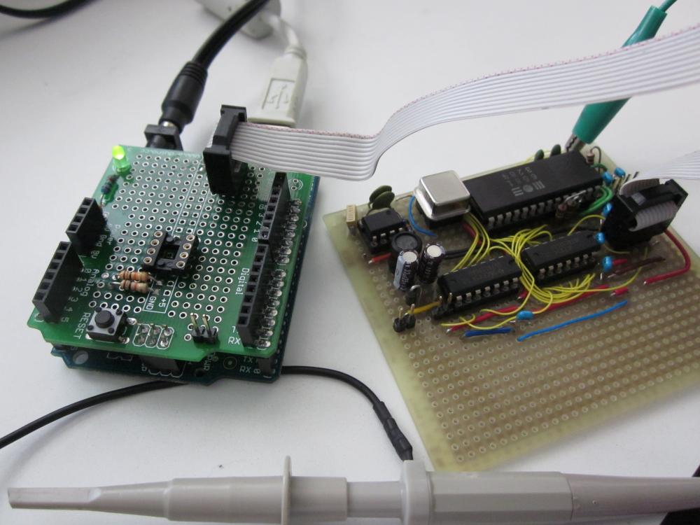
Update: results here.