 |
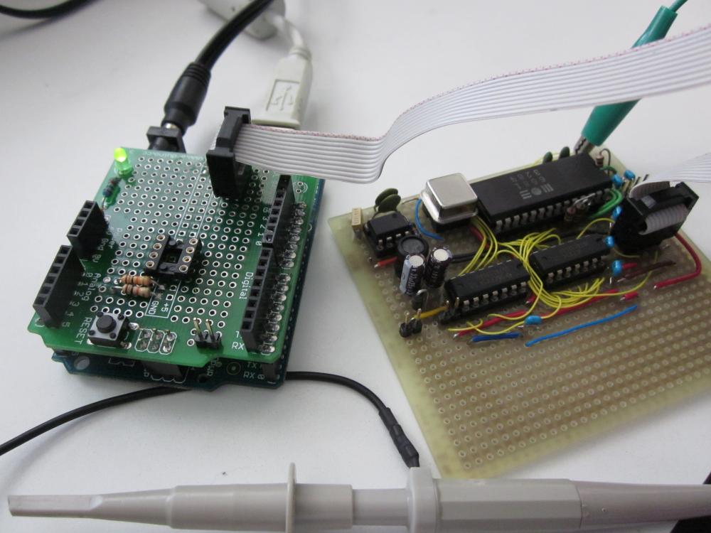
| Arduino (under Protoshield) with SIDshield prototype fully populated |
Power Considerations
The SID needs up to 100mA on the 12V line (according to the datasheet), so about 1.2W of power. The TPS6734 has to produce that power from 5V, and thus needs to draw more than twice the current off that supply. Clearly, this is too much for a USB port, thus the Arduino must be connected to a power supply. Also take note that the barrel connector is going through a regulator with associated voltage drop (at least on my Arduino Diecimila) so your supply needs to give more than 5V.
A further complication is that the TPS6734 regulates really well for a range of input voltages; this means it has an effective negative resistance: if the input voltage drops (say, to 4V) it will draw more current; this could lower the voltage even further. We have a positive feedback loop, ending when the supply voltage drops below what the boost converter can use and we loose the 12V. Milliseconds later, the converter starts up again (since it did not draw any current and the supply recovered) and the process begins anew. Needless to say, this does not sound good on the output. So, give the poor SID a good supply!
One could argue of course that the better solution is to provide a good stable 12V supply and drop in a good old 7805 to supply the Arduino - this is why we build prototypes, right?
BTW, with all this power being sucked up, the SID gets pretty warm, I tell you...
Corrections and Changes to the Schematic
The circuit even when supplied with good power on the Arduino external power barrel connector gives a bit of noise when playing large amplitude sounds. This probably needs some resizing of capacitors when compared to the circuit given in the TPS6734 datasheet.
I also moved the reset line of the SID to a programmable (Digital Out) pin, and toggle that line in the SID library constructor.
The biggest error in the schematic posted in a previous post is that the capacitors on the input and output lines are far too small. 22pF? I have no idea how that got in there - they need to be about .1uF! I need to fix that on the board.
The hardware is thus effectively finished, needing just a few corrections. I will update the schematic eventually, including the boost converter. The main to-do is now some more code, especially to get steady timing, which is vital for good sounding vibrato, tremolo, and arpeggio effects - not to mention basic song timing.
However, there are a pile of other projects I've been itching to do...
The SID needs up to 100mA on the 12V line (according to the datasheet), so about 1.2W of power. The TPS6734 has to produce that power from 5V, and thus needs to draw more than twice the current off that supply. Clearly, this is too much for a USB port, thus the Arduino must be connected to a power supply. Also take note that the barrel connector is going through a regulator with associated voltage drop (at least on my Arduino Diecimila) so your supply needs to give more than 5V.
A further complication is that the TPS6734 regulates really well for a range of input voltages; this means it has an effective negative resistance: if the input voltage drops (say, to 4V) it will draw more current; this could lower the voltage even further. We have a positive feedback loop, ending when the supply voltage drops below what the boost converter can use and we loose the 12V. Milliseconds later, the converter starts up again (since it did not draw any current and the supply recovered) and the process begins anew. Needless to say, this does not sound good on the output. So, give the poor SID a good supply!
 |
| The multimeter shows the draw on the 5V line, including the Arduino. The scope shows the noise on the 12V line, which is 1Vp-p and about 100mV RMS. Noise control needs to be improved. |
BTW, with all this power being sucked up, the SID gets pretty warm, I tell you...
Corrections and Changes to the Schematic
The circuit even when supplied with good power on the Arduino external power barrel connector gives a bit of noise when playing large amplitude sounds. This probably needs some resizing of capacitors when compared to the circuit given in the TPS6734 datasheet.
I also moved the reset line of the SID to a programmable (Digital Out) pin, and toggle that line in the SID library constructor.
The biggest error in the schematic posted in a previous post is that the capacitors on the input and output lines are far too small. 22pF? I have no idea how that got in there - they need to be about .1uF! I need to fix that on the board.
The hardware is thus effectively finished, needing just a few corrections. I will update the schematic eventually, including the boost converter. The main to-do is now some more code, especially to get steady timing, which is vital for good sounding vibrato, tremolo, and arpeggio effects - not to mention basic song timing.
However, there are a pile of other projects I've been itching to do...
No comments:
Post a Comment