ASCIIMath creating images

Showing posts with label Classic Computing. Show all posts

Wednesday, January 3, 2018

A trip to the library...

When I started thinking about resampling and the filters used in resampling I leaned heavily on the book by P. P. Vaidyanathanm, "Multirate Systems And Filter Banks", the "brown book" that every signal processing practitioner should have on his or her shelf (or on a shelf of a nearby colleague)!

Like many articles discussing this topic (e.g. the documentation of this MATLAB function), the key paper always referenced is Kaiser, James F. “Nonrecursive Digital Filter Design Using the I0-Sinh Window Function.” Proceedings of the 1974 IEEE International Symposium on Circuits and Systems. April, 1974, pp. 20–23. Being curious about how the equations given in Vaidyanathanm were derived, I wanted to see the original paper - but unfortunately, the earliest proceedings of ISCAS that can be found in IEEE Xplore are from 1988 - 14 years after the one I'm after.


Luckily, I happen to be on Christmas vacation at my inlaws, which live in Kitchener, which is right next door to Waterloo - home to one of the best engineering universities of the world. Unsurprisingly, they have a well-stocked library, which includes the above conference proceeding booklet and, braving the cold, I now have a copy for my own archives.

I could only copy it by taking snaps using my cellphone - the copiers need a special card to use, and the scanners need a UWaterloo login, but for reading the content, that is sufficient with today's smartphones.  It's only for personal use, and I do hope that the IEEE will eventually get around to scanning in the older papers!

Papers from that era have a certain charm.  Typewriter written equations.  FORTRAN code.  I believe the below should be FORTRAN66 (due to the IF statement; I don't think FORTRAN IV had that, and FORTRAN77 obviously didn't exist yet).  Without looking it up, do you know how that IF statement works? (Explanation at end)

As for what I learned from the paper (on first quick read): those formulas relating N and beta to the Stopband attenuation and transition band width were fitted to empirical data.  I expected as much - but still I wanted to confirm that to myself. (If on a closer read I turn out to be wrong, I'll correct this post)

So there's one item off my list of things to to in 2018. Visit the UWaterloo Campus and its library.  Good fun.

-------

The FORTRAN IF statement: That is known as the "arithmetic IF" or "three-way IF" statement. The expression after the IF is evaluated, and if it is negative, the execution jumps to the first label ("2", exiting the subroutine). If the result is 0, we go to the second label ("1"), and if it is positive, to the third (also "1").  Here, each term of the power series expansion is calculated, and as soon as the new term is less than 2x10^-9 of the approximation, the code terminates. And IIRC, FORTRAN is call-by-reference.

Thursday, August 30, 2012

Panasonic HHC Schematics by Tony Duell


(TL;DR version: the scans are here)

Some years ago, I picked up a Panasonic HHC, having had an interest in the small hand-held BASIC computers for a while.  As it turns out, the HHC does not use basic at all, and is by default not really "open" in any way - there was a BASIC ROM available, but generally the thing was used as a specialized calculator with custom ROMs.  Still, It's a cute little machine with the interesting feature of using a 6502 inside, and it came with a printer that uses regular paper, and even the internal batteries still work.

Recently, there was a discussion about it on the Classiccmp mailing list, and Tony Duell - known for his classic computer electronics acumen if not his take-no-prisoners approach to typing emails - mentioned that he had traced out the circuits of this little machine.  This got me (and several others) interested, and he offered to make these available to the general public if someone would scan them and place them somewhere on the web.  The physical pieces of paper from Tony were scanned by Dave Colver, who in turn sent me the images.  I did a bit of cleaning up (nothing more than adjusting levels to remove some JPG compression artifacts) and collated them into a PDF document and you can download them from here: Panasonic HHC RL-H1400 Schematics.

Unfortunately, my HHC is at this moment a couple of thousand kilometers away, in a box at a friend's house in Pointe-Claire, Canada.  However, once I live in a place where I have a workshop again, I will mess around with it, for sure.  Dumping the ROMs would be a good start!

Saturday, June 16, 2012

Classic Computing Redux

When I accepted my current Postdoc position, knowing it would mean a move from Canada to France, I decided to all but completely dissolve my classic computer collection.  I just kept my Commodore 8-bitters, that are now in boxes at a friend's place in Pointe-Claire, QC.

However, here in Rennes (and probably everywhere else in France) there are a lot of "braderies", basically organized neighborhood garage sales; we have found these to be a great source of things we need.

And sometimes, one sees something that can't just be left.  Like this Commodore 4-op calculator (Model 776M).  For €1.  No, I won't hack it, it's just too damn cute.

Friday, July 22, 2011

SIDshield prototype: test results

For those interested in this project (both of you!) :-) I finished the testing of the SIDshield prototype. Summary: It works! (Yay!) but with caveats and a few fixes are needed (booo!)
Arduino (under Protoshield) with SIDshield prototype fully populated
After cleaning, visual inspection and continuity check (see yesterday's post) I found I forgot 3 wires - one to connect the grounds together, and 2 for getting the 12V to the SID chip. Thus fixed, I populated the board with all chips except for the SID and applied power. Seeing no magic blue smoke escape, I measured the 12V supply, which looked very good (without load of course) giving me ~12.4V. All other signals on the SID socket looked good so I put it in, applied power again and verified the voltages again. Same as without load.

Power Considerations
The SID needs up to 100mA on the 12V line (according to the datasheet), so about 1.2W of power. The TPS6734 has to produce that power from 5V, and thus needs to draw more than twice the current off that supply. Clearly, this is too much for a USB port, thus the Arduino must be connected to a power supply. Also take note that the barrel connector is going through a regulator with associated voltage drop (at least on my Arduino Diecimila) so your supply needs to give more than 5V.

A further complication is that the TPS6734 regulates really well for a range of input voltages; this means it has an effective negative resistance: if the input voltage drops (say, to 4V) it will draw more current; this could lower the voltage even further. We have a positive feedback loop, ending when the supply voltage drops below what the boost converter can use and we loose the 12V. Milliseconds later, the converter starts up again (since it did not draw any current and the supply recovered) and the process begins anew. Needless to say, this does not sound good on the output. So, give the poor SID a good supply!

The multimeter shows the draw on the 5V line, including the Arduino.  The scope shows the noise on the 12V line, which is 1Vp-p and about 100mV RMS.  Noise control needs to be improved.
One could argue of course that the better solution is to provide a good stable 12V supply and drop in a good old 7805 to supply the Arduino - this is why we build prototypes, right?

BTW, with all this power being sucked up, the SID gets pretty warm, I tell you...

Corrections and Changes to the Schematic
The circuit even when supplied with good power on the Arduino external power barrel connector gives a bit of noise when playing large amplitude sounds. This probably needs some resizing of capacitors when compared to the circuit given in the TPS6734 datasheet.

I also moved the reset line of the SID to a programmable (Digital Out) pin, and toggle that line in the SID library constructor.

The biggest error in the schematic posted in a previous post is that the capacitors on the input and output lines are far too small.  22pF?  I have no idea how that got in there - they need to be about .1uF!  I need to fix that on the board.

The hardware is thus effectively finished, needing just a few corrections. I will update the schematic eventually, including the boost converter. The main to-do is now some more code, especially to get steady timing, which is vital for good sounding vibrato, tremolo,  and arpeggio effects - not to mention basic song timing.

However, there are a pile of other projects I've been itching to do...

Wednesday, July 20, 2011

SIDshield prototype almost done

I've finally gotten around to doing some electronics again, and finished wiring up the full prototype of the SIDshield for Arduino.  Soldering and wiring got done yesterday, later today I will go over the whole thing very carefully to check for shorts and broken connections/wires, make sure GND and power are everywhere they're supposed to be.  Then, I will plug in everything except for the SID and apply power, to make sure the magic smoke stays in; only then will I plug in the SID since it's a not-easily-replaced chip.

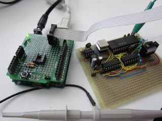
Component side

It's not a "real" schield in this format, but I decided it was better to separate it from the Arduino using a ribbon cable.  Still, the whole thing is in a 8cm x 5cm rectangle.

Solder side
I'll post the results of checking and testing either tonight or tomorrow.
Update: results here.

Wednesday, March 9, 2011

SIDshield on hiatus for a short time

For the few folks who have been looking at the SIDshield project, just a quick note that I will not be updating anything about it for the next few weeks.  At the end of this month (March 2011) I will be defending my Ph.D. thesis, so I need to prepare for that.  Afterwards, I'll be taking a couple of weeks of vacation, away from my tools (but closer to mountains and forests and stuff).

Once I'm back, I'll be ordering the parts to build a properly soldered prototype.

I might still make the occasional post about MATLAB, LaTeX, Python, Mercurial or whatever else takes my fancy but not too much time.

...oh, and anyone knowing of open post-doc positions with focus on audio signal processing (preferably in Europe, Canada or Australia/NZ) feel free to shoot me a line... :-)

Friday, February 25, 2011

SIDshield code updated

I have updated the code for the SIDshield, now it's actually useable to play some music in a relatively easy way.  Here is the new library, and here is a simple player with a little melody.  The player code is basically ported from the SIDcog, including the stored melody - so that remains copyright "Ahle2"! (Who deserves lots of respect for writing SIDcog)

The biggest problem with my code is that I didn't spend much effort in getting the timing correct so it's a bit wonky.

NOTE the Arduino environment puts static tables in RAM, which is very limited especially on the Atmega168.  I would constantly get mysterious malfunctions, including the inability to upload new sketches - effecitvely "bricking" the Arduino.  This can be fixed by carefully removing and resetting the power using the jumper and timing the upload of a new sketch.  It took me quite a while to figure out the solution.

The solution is to ensure the music data is in program memory: using the PROGMEM keyword.  Its use is a bit involved, since one can't simply access it as arrays but has to explicitly copy it using special functions.  See the player app.

UPDATE: The files got moved to my homepage, I adjusted the links accordingly.

Tuesday, February 22, 2011

Arduino SIDshield initial schematic and code

This is the schematic for the Arduino SIDshield I've been working on, drawn using Eagle. This is NOT the circuit on the breadboard, since I don't have a couple of 74LS164's handy - instead, I used a pair of 74LS323's that are slightly more flexible.  They operate in a simple parallel out mode though.  Also, as mentioned in the previous post, the 1MHz clock is provided by a function generator buffered by a 74LS04.  Hence, regard this schematic as untested!

I still haven't gotten around adding the 5V-to-12V boost circuit.  I was planning on using the LT1109CZ-12 - a nice, small TO-92 packaged chip.  Unfortunately it's not easy to get, it seems.  My 6581 draws 27mA from the 12V supply, well within the limits promised bu Commodore (datasheet says 25mA typ, 40mA max).

Software

The library to drive the chip is a modification of the Spi library, reduced to the constructor and a single function.  I will add more functions later, for now all it does is take an address and data value and set the appropriate SID register.  This first version is on my website.  A simple sketch to test it:

#include <SID.h>

void setup()
{
  sid.setReg(24,15); // full volume
  sid.setReg(6,0xf0); // ADSR=0,0,15,0
  sid.setReg(1,0x1c); // set frequency to 440Hz
  sid.setReg(0,0xd6);
}

void loop()
{
  // .8s beep at 1s interval
  sid.setReg(4,17); // gate on
  delay(800);
  sid.setReg(4,16); // gate off
  delay(200);
}

Performance

The speed with which registers are written is pretty good.  I don't want to make it any shorter actually, since the chip select is not synchronized to the clock signal - so I have to make sure a few cycles happen during CS low.  The shift registers get loaded within 5us, and the CS signal is asserted for slightly less than that.  Overall the entire operation of setReg is about 15us.

More to come.
UPDATE: see here.

Thursday, February 17, 2011

Arduino SIDshield: it's ALIVE!!!!

My most recent little project is to make a good ol' Commodore SID chip (6581) be controlled by an Arduino.  The prototype is now functioning:
The breadboard with the Arduino, the SID chip, a couple of shift registers, and a clock buffer.
The complete setup requires a bit more hardware:
Ok, quite a bit of that stuff is redundant...
On the scope you can see the triangular wave I coaxed out of the chip, which was pulled from my first C64, bought back in 1984 or 1985 in Germany.

This weekend I will finalize the schematics, do a board layout and finish the library for the Arduino.  Note that the design is conceptually very similar to the MIDIbox SID module, but then there are only so many ways to attach a SID to a couple of shift registers.

The final version will use a crystal oscillator (replacing the function generator in the picture) for the 1MHz clock, and a DC-DC boost converter to generate the 12V for the SID (currently provided by the adjustable supply).

I will post the schematic, layout and code as soon as I'm done.